How to install digital trigger unit V1.7 light sensor version for V2 gearbox?
Share
Installation steps
Step1:
Find these two sponge pads in the parts bag before starting the machine, and tear off the yellow adhesive at the back.

Step2:
Paste it on the top of the pins.
Step3:
Press the pad down and let the pins go through it.
 Step4:
Do another pad the same way.
 Step5:
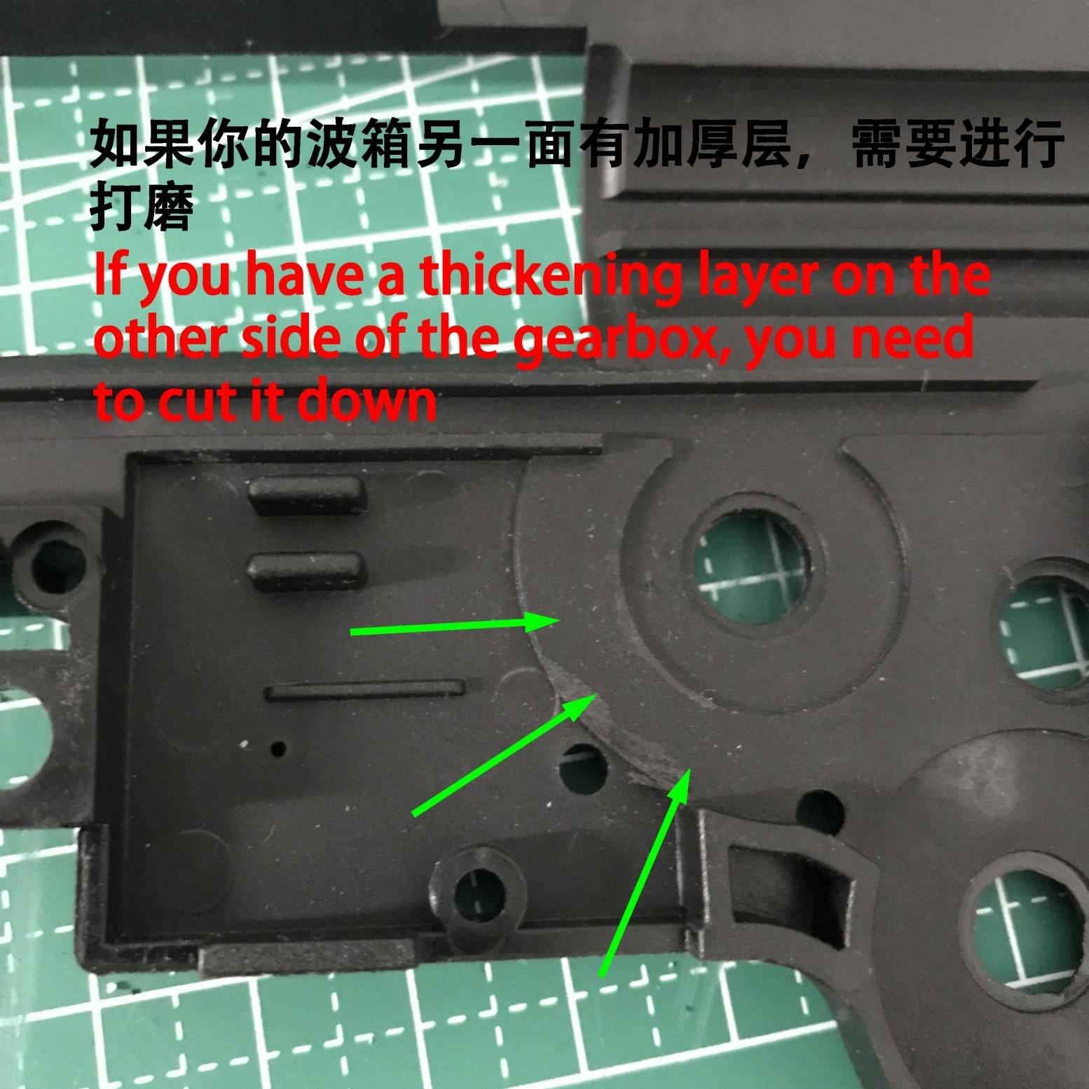
If you have a thickening layer on the other side of the gearbox,you need to cut it down.

Step6:
Use the top plate to measure the position to be polished,and the convex structure position in the green circle needs to be completely removed.

Step7:
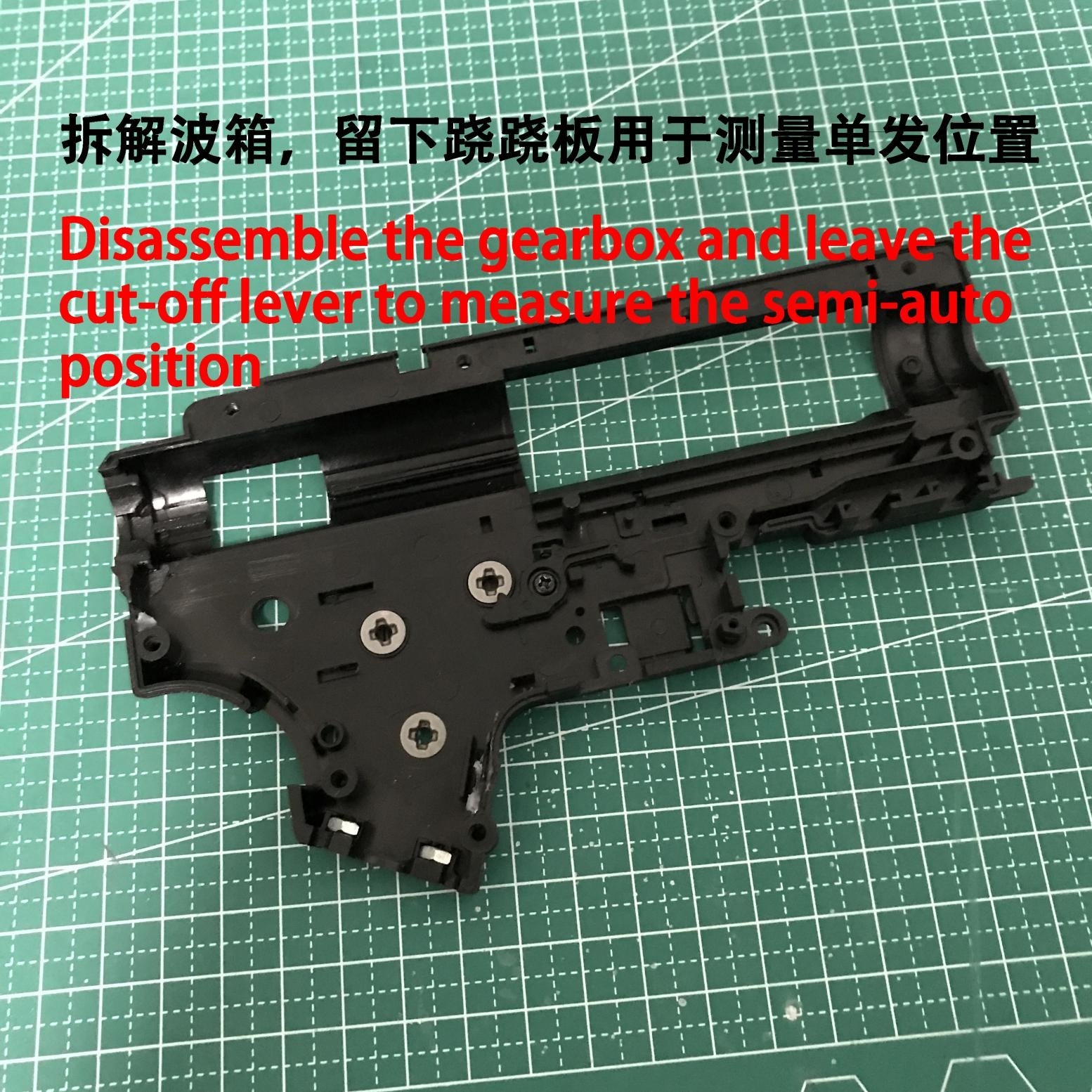
Disassenble the gearbox and leave the cut-off lever to measure the semi-auto position.

Step8:
Make the cut-off lever in the horizon position,side the selector plate to the left against the lever,which is the semi-auto position.
Selector sensor should be here(Blue Arrow).The detective range of the sensor is 0.5-1mm.
 Step9:

Step10:
Stick on the attached white sticker and black the left side of the green line.
The plane of the white paper should be within the range of 0.5-1mm of the sensor.(Arrow Pointing)
If your selector sensor cannot detect the white paper,you need to change the thickness of the white paper.
 Step11:
Start to install the circuit board,first put the bottom board into the gearbox,align with the screw hole,if not,please make the corresponding compatibility modification.

Step12:
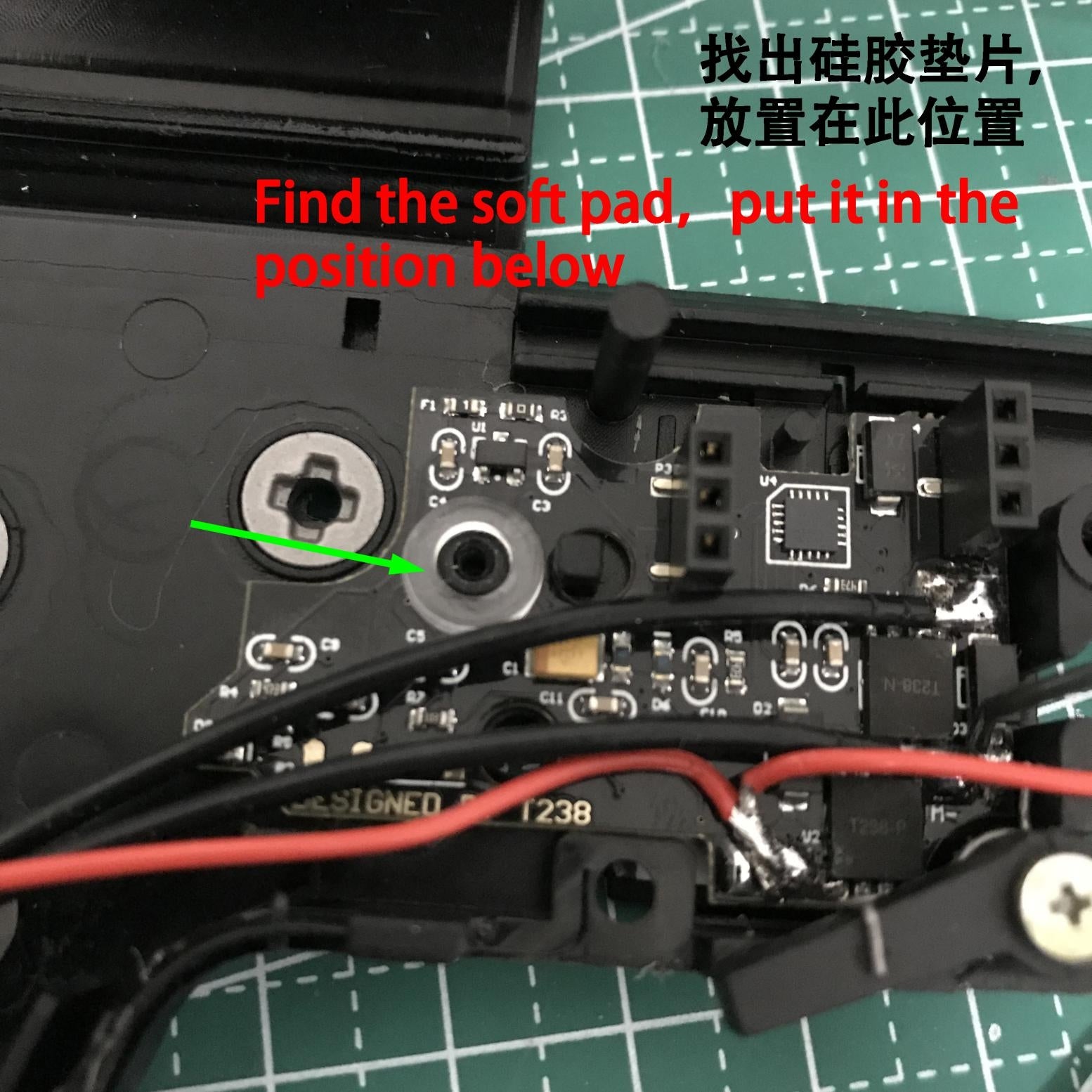
Find the soft pad,put it in the position below.

Step13:
Make sure the circuit board does not tilt,tighten the screw.

Step14:
Lay out the wires,do not block the sensors.

Step15:
Put other parts back to their original positions to ensure that the trigger has enough rotation angle,otherwise the parts in the green circle need to be modified.

Step16:
Make sure that the circuit board does not affect the rotation of trigger,otherwise the parts in the green circle need to be modified.
Notice(As shown):
The gap of this kind of trigger is too large,which needs to be covered with black tape.

Step17:
After alignment,insert the DTU top board gently,without pressing to the bottom.

Step18:
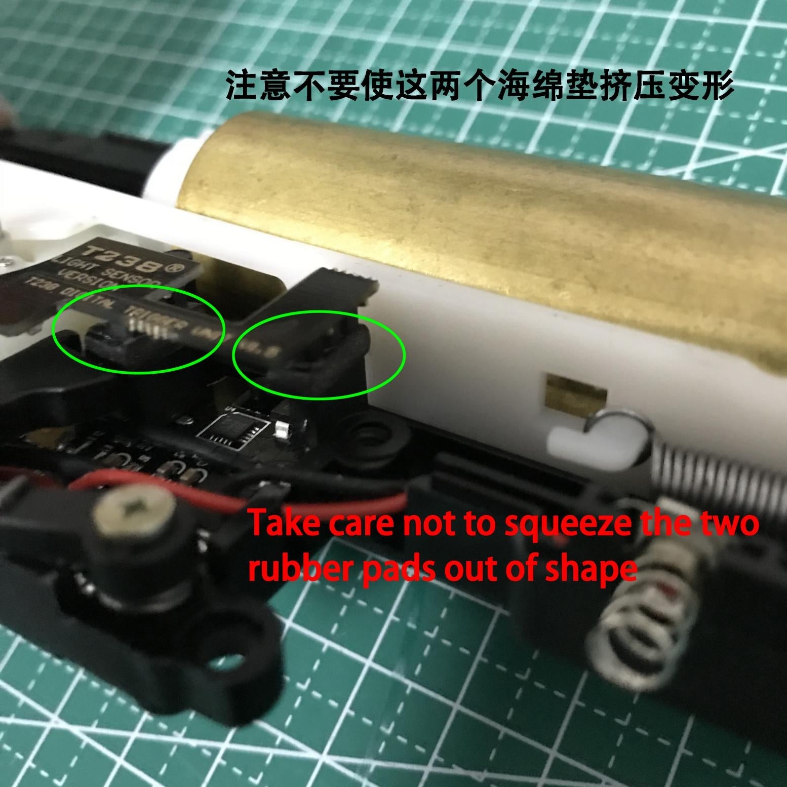
Take care not to squeeze the two rubber pads out of shape.

Step19:
Close the gearbox and tighten all screws.


