
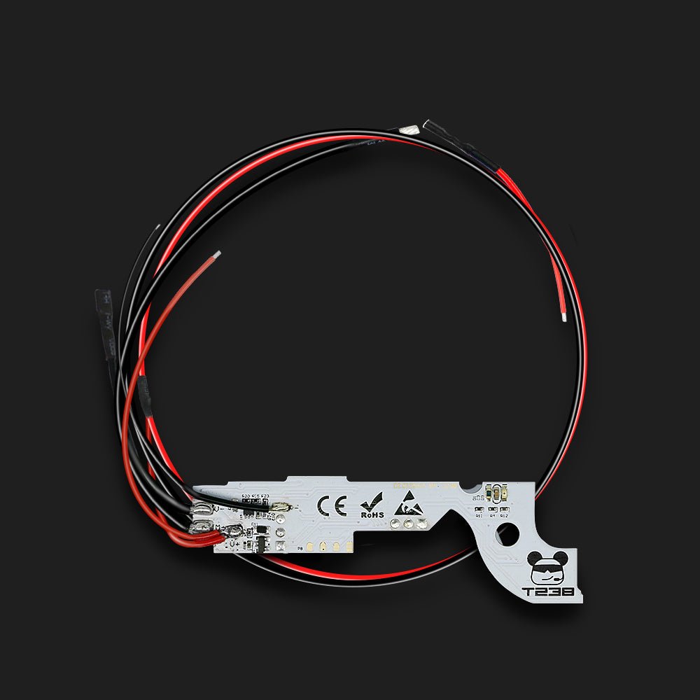
How to install digital trigger unit 2.0 Bluetooth Version for V3 gearbox?
Installation steps
1.Attach the attached transparent sticker in the green area for insulation.
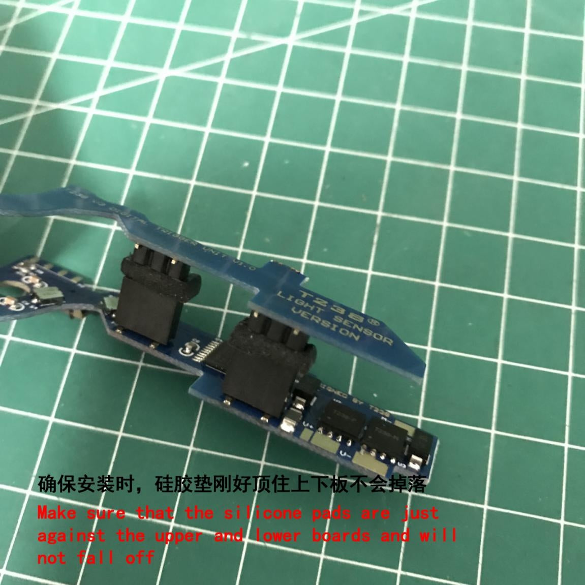
2.Find these two silicone gaskets with back glue in the attached parts kit.

3. Remove the yellow paper on the back.

4.Stick it to the pinheader on the top board of DTU.

5.Press the gasket to the bottom,let the pins go through it.

6.Make sure that the silicome pads are just against theuper and lower boards and will not fall off.
7.The white part is a little thicker than the shell,shall be cut off to the same thickness of the shell to prevent interference with the circuit board.
8.Cut off this part for about 1mm, it will not interfere with the circuit board and the safety function still works.

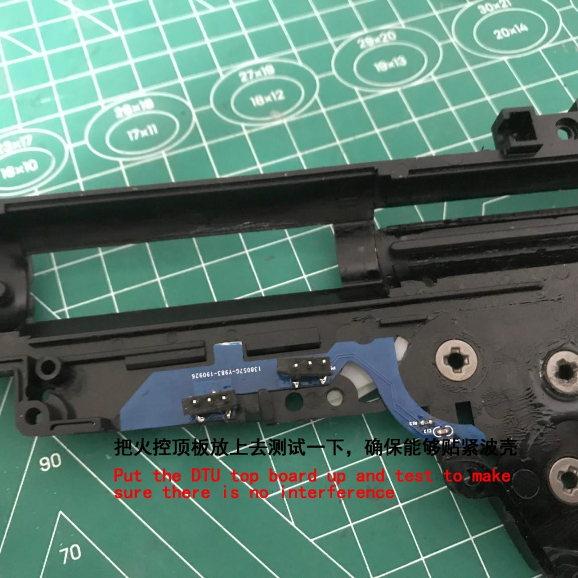
9.Put the DTU top board up and test to make sure there is no interference.
10.Remove all the internal parts of your gearbox and install the DTU bottom board in the position shown in the figure.It is recommended to shim your gearbox before installing DTU.
When installing the trigger components,be sure to observer these two detection switvhes and do not crush them!(Arrow Pointing)
11.Lay out the wire,then install the sector gear.

12.Carefully align the pins of the top board and the sockets of the bottom board,after alignment,press the top board gently to make the pins enter the sockets slowly,please DO NOT press firmly to the bottom to make the silicone pads deform,when the gearbox is closed,the silicone pads will be deformed to adapt to the inner space of the gearbox automatically.

13.Install other parts inside the gearboc back to the original position,and the lever and mechanical trigger switch do not need to be installed.
When installing the trigger components,be sure to observe these two detecion swithches and do not crush them!(Arrow Pointing)

14.Close the wave box and tighten the screws when there is no error.

15.As shown in the figure,the DTU to and bottom circuit boards should be close to the upper and lower inner surfaces.

16.Lay the wires according to your blaster type.
When the trigger is pulled to the bottom, the angle of the slider should be close to the contour line of the circuit board, as shown in the green line in the figure, otherwise the trigger slot needs to be expanded.


Properly put a gasket on the trigger slider shaft to ensure that there is no gap between the slider and the lower gearbox to prevent light leakage. If there is a gap between the green arrow and the gearbox in the figure, it is recommended to place a gasket.

Stick the sticker on the outside of the selector plate to ensure that the selector plate can cover the sensor of the full-auto when sliding to the full-auto position (G36 is the full-auto position and AK47 is the semi-auto position), and the sensor of the full-auto is not covered when sliding to the semi-auto position (G36 is the semi-auto position and AK47 is the full-auto position). It is recommended that the surface of the gearbox and the selector plate near the selector are mainly black and dark, otherwise they are painted black.


The specific position of the sticker is mainly based on the actual situation, which needs to be adjusted repeatedly to ensure the accurate position of full-auto and semi-auto.